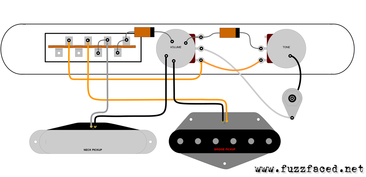
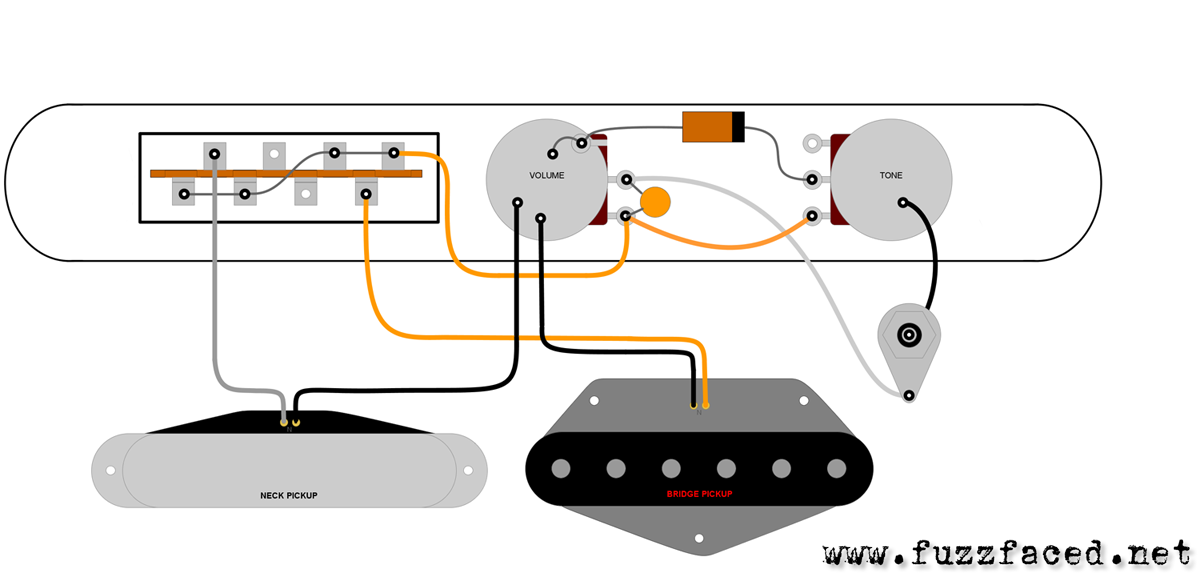
Until the late '60s, all Telecasters (and the Esquire, until it went out of production) featured waxed cotton insulated wires (a.k.a. “cloth wires”). On the regular dual and single pickup assemblies, the color of the wires is usually black for ground and white (neck pickup) or yellow (bridge pickup) for hot. Exceptions do exist though, particularly on mid-'60s guitars which may come with blue or green ground wires.
Beginning in 1968, cloth-wires were gradually replaced by plastic-coated wires.
Cloth wires were later resurrected for the '52 Vintage Reissue Telecaster, although the very first units were actually fitted with plastic wires.
All the 1950 Telecaster-style guitars featured slot heads screws. In 1951, Fender started a gradual transition towards Phillips heads screws, but until the summer of 1953 Phillips head could be still used for holding the bridge pickup and the selector switch, because Leo Fender didn’t want to waste anything.
PROTYPES AND PRE-PRODUCTION GUITARS
The snakehead prototype featured a small rectangular control plate with only two knobs, whilst the second prototype was originally fitted with a football shaped plate, which in 1956 was replaced with a Precision Bass one anchored in a different position.
Other pre-production Esquires featured a shorter control plate and a push pull organ style button because in the beginning Leo Fender didn’t have a dual pickup guitar in mind, so there was no need to accommodate space for a selector switch on the control plate. The push pull switch produced a signal cut similar to the wah wah effect.
By the Summer of 1950 Leo Fender replaced the push pull switch with the 3-way switch on the single pickup Esquire - once he’d decided to manufacture the two-pickup model too – and a longer (6.27”) control plates became the standard trim after Summer 1950.
It's interesting to note that the ground leads from the pickups were soldered to the selector plate in pre-production single and dual pickup assembly, whilst they were soldered to the volume pot in production Esquires and Broadcasters.
PRODUCTION GUITARS SINGLE PICKUP ASSEMBLY
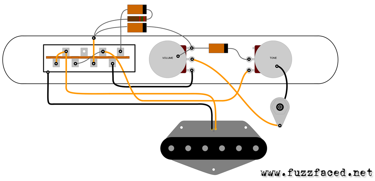
With the 3-way switch in the first position, the electric signal reached the pickup without passing through the tone pot, in the central position the pickup was normally connected to the volume and tone, and in the third position the pickup was connected to a circuit that included a resistor and two capacitors so as to produce a sound that cut treble and which Leo called “deep rhythm”, because it allowed guitarists to play the bass parts. The 2nd control operates only in the middle position but it works as a real tone control.
Electronically speaking, this assembly features:
- POSITION 1 = the pickup is directly wired to the output jack to give a hotter lead sound with no tone control.
- POSITION 2 = the pickup is normally wired through volume and tone controls
- POSITION 3 = the pickup is wired through two capacitors and one resistor to offer a pre-set bassy sound with no tone control
Electronically speaking, this assembly features:
- Two 250K Ohm audio pots for the controls
- Three .05 MFD capacitors
- One 2.5K resistor, later replaced by a 3.3K resistor after the mid-'50s
DUAL PICKUP ASSEMBLY: 1950 - Early 1952
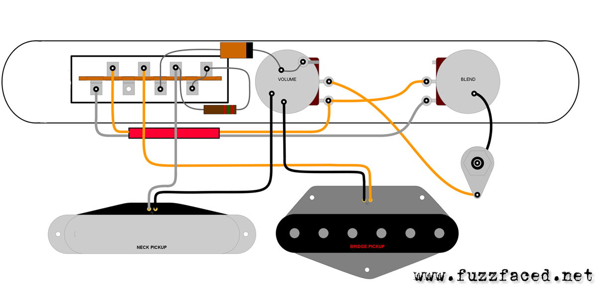
Dual Pickup Esquire Broadcaster, No-Caster and early Telecaster guitars had a 3-way switch, a volume knob and a “blend” knob – used to mix the neck pickup with the bridge pickup in the lead position. Therefore, there was no tone control. In the lead position the blend knob would mix the neck pickup with the bridge pickup, in the central switch position only the neck pickup was activated, with no tone control, whilst the third switch position activated the neck pickup (again without tone control), but this time the signal travelled through a capacitor which cut treble to give the “deep rhythm” effect.
This wiring continued to be used on two-pickup Fenders until around the end of 1952.
Electronically speaking, this assembly featured:
This wiring continued to be used on two-pickup Fenders until around the end of 1952.
- B = both pickups together with the neck pickup “blended” into the bridge pickup according to the setting of the 2nd “tone” control
- M = neck pickup alone with a natural sound and no blend control
- N= neck pickup alone with a pre-set deep rhythm effect sound and no tone control
Electronically speaking, this assembly featured:
- Two 250K Ohm audio potentiometers for the controls
- One .05 MFD capacitor connected between the switch and the master volume pot
- One 15K Ohm resistor soldered on the CRL switch
DUAL PICKUP ASSEMBLY: MID 1952 - 1967
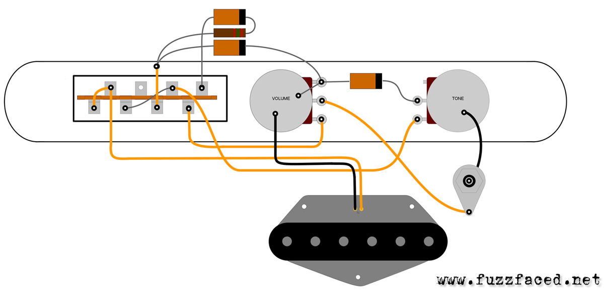
During the 1952 Leo Fender changed the Telecaster’s electronics, replacing the blend with a tone control, discarding any two pickup combination. So now, the first switch position activated the bridge pickup connected with the tone control, the central switch position the neck pickup with the tone control and the third position the neck pickup with the capacitor that further cut treble, producing the “deep rhythm” effect Leo liked. It was only accidentally that guitarists discovered, thanks to this wiring, that if the selector was left hanging between the first two switch positions the two pickups could be combined to give unexpected sounds.
Electronically speaking, this second variant features:
It's important to note that many players clipped off the .1 MFD capacitor connected between the switch and the volume pot. Others completely rewired the assembly to obtain a classic 2-pickup switching.
- B = bridge pickup alone with the tone control
- M = neck pickup alone with the tone control
- N = neck pickup alone with a pre-set deep rhythm effect sound and no tone control
Electronically speaking, this second variant features:
- Two 250K Ohm audio pots for the controls
- One .05 MFD capacitor connected between the 2 pots
- One .1 MFD capacitor connected between the CRL switch and the master volume pot but it no longer incorporates a 15K resistor soldered on the selector switch
It's important to note that many players clipped off the .1 MFD capacitor connected between the switch and the volume pot. Others completely rewired the assembly to obtain a classic 2-pickup switching.
DUAL PICKUP ASSEMBLY: AFTER LATE 1967
The wiring was finally modified in late 1967 to provide a traditional 2-pickup switching, discarding the pre-set deep rhythm effect sound.
Electronically speaking, this wiring initially featured:
By late 1981 the tone pot reverted to 250K instead of 1 MEG and in 1983 the tone capacitor was changed for a less bassy .022 MFD.
In late 1987, the American Standard came out with a modified circuitry featuring a TBX tone control, first introduced in 1983 on the Elite Telecaster. The TBX control featured a dual concentric pot (250K audio/1 MEG linear), one .022 MFD capacitor and a 82K resistor. At the same time, the volume pot reverted to 250K instead of the 1 MEG value in use since 1969.
- B = bridge pickup alone with tone control
- M = both pickups together with tone control
- N = neck pickup alone with tone control
Electronically speaking, this wiring initially featured:
- two 250K Ohm audio pots for the controls
- one .05 MFD capacitor connected between the 2 pots
- one .001 MFD capacitor soldered on the volume pot for added brilliance at lower settings
By late 1981 the tone pot reverted to 250K instead of 1 MEG and in 1983 the tone capacitor was changed for a less bassy .022 MFD.
In late 1987, the American Standard came out with a modified circuitry featuring a TBX tone control, first introduced in 1983 on the Elite Telecaster. The TBX control featured a dual concentric pot (250K audio/1 MEG linear), one .022 MFD capacitor and a 82K resistor. At the same time, the volume pot reverted to 250K instead of the 1 MEG value in use since 1969.
OTHER PICKUP ASSEMBLIES
THINLINE
At first, the Telecaster Thinline featured a post-67 standard dual-pickup wiring. In late 1971, the model was revamped with two Fender Wide Range Humbucking Pickups, but kept the same controls arrangement (master volume and tone controls with a 3-way switch). However, with the advent of humbuckers, the value of the pots changed from 1 MEG to 250K and the tone capacitor switched from .05 MFD to .022. Besides, the .001 MFD capacitor added in late 1967 to the volume control of the standard assembly was also discarded.
CUSTOM (TYPE II)
The original Telecaster Custom model shared the same electronics as the regular Telecaster. When it was revamped in 1972 with the Fender Wide Range Humbucking Pickup in the neck position, it featured a 4-control assembly, with separate volume and tone settings for each pickup. With the advent of the humbucker, it kept 1 MEG pots, but .022 MFD capacitors were adopted for the tone controls.
DELUXE
The Telecaster Deluxe with its two humbuckers, a 3-way toggle switch and four knobs, resembled a Gibson guitar. As the Telecaster Custom, it was fitted with four 1 MEG pots (two volume and two tone controls) with one .022 MFD capacitor on each tone control.

